IPA1 & IPA2 information
Amplifier Conversion Information
In all, there are six amplifier types: three frequency ranges and two power levels:
| Name | Original Range | Conversion Information Available |
| To 50-52 MHz | To 52-54 Mhz | To 144Mhz | To 222MHz |
| 1kW Amps |
| lo-lo | 54-72 MHz (Chs. 2 through 4) |
INFO |
Not Necessary |
INFO |
NO |
| lo-hi | 76-88 MHz (Chs. 5 and 6) |
INFO |
INFO |
INFO |
NO |
| hi | 174-216 MHz (Chs. 7 through 13) |
NO |
NO |
possible |
Not Necessary |
| 1.5kW Amps |
| lo-lo | 54-72 MHz (Chs. 2 through 4) |
possible |
Not Necessary |
INFO |
NO |
| lo-hi | 76-88 MHz (Chs. 5 and 6) |
possible |
INFO
| INFO |
NO |
| hi | 174-216 MHz (Chs. 7 through 13) |
NO |
NO |
possible |
Not Necessary |
In addition to the final amplifiers, there are two intermediate power amplifier stages - IPA1 and IPA2. These are described here.
W1BRI photo
Background
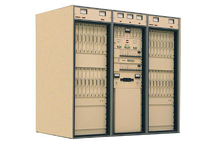
A well respected Canadian company named
Larcan was the first manufacturer of a
100% solid-state, high power VHF television transmitter.
These transmitters used hot-swap 1kW PA modules to combine power up to
85kW. The Larcan philosophy was and still is "KISS". The
reliability of Larcan VHF transmitters has been phenomenal.
Much like the post-WII surplus radio era and later commercial two-way
radio surplus era, the potential for a second long lifetime in high-power
amateur service is compelling.
click image for more details
More Information
Advance to 2010. The original model 1kW FET PA module debuted in 1987 and is still
in production today. This may become the TV surplus equivalent of
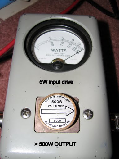
a GE MASTR-II ! In a May 8th 2006 test at Larcan's
Mississauga, Ontario production line, a 53 MHz carrier was introduced
into a low-split lowband VHF transmitter power amplifier module. To no
surprise with ten-watts of drive, this PA made a full 1kW output with video modulation (similar to SSB)
and a solid 600-Watts when in CW/FM. This CW test is essentially the same as
comparatively narrowband 5KHz modulation when used for FM
voice communications.
To be conservative, the PA's are rated at a minimum of
20dB gain when on the correct frequency. However, spec sheets from factory testing of a standalone PA
typically yields 22dB gain.
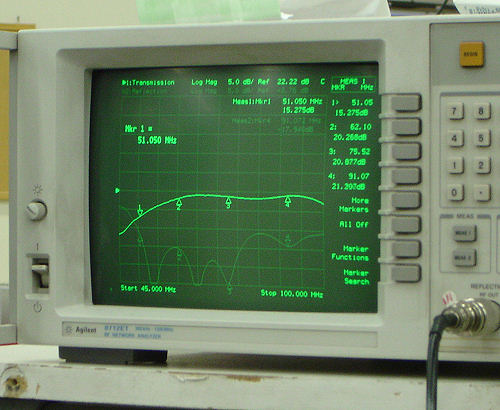
| 5dB per div sweeping
45-100 MHz on a high-split lowband VHF PA (77-88 MHz) under test at 51.050 MHz.
Expect a cool 300W+ FM even when used out of the default
factory spec.
Expect a full 600W FM/CW when using a low-lowband split PA at 51 MHz (54-77 MHz factory spec).
The simple chip cap and jumper mods below will bring a high-split lowband PA
into the low-split lowband frequency range at full specs.
W1BRI photo
(more
info here)
Many PA's exhibit 22dB gain but 20dB is spec. When operating out of factory spec with
no mods (high-split lowband), expect the overall PA gain to
reduce from 20dB to 15dB. Only a few
jumper and chip cap changes are required to convert a
high-split lowband PA into low-split lowband at a full 600 Watts FM.
But even with no cap changes 300-Watts is plenty of power
for most uses. You can also get by with a smaller
power supply at 300 Watts.
Suggestion:
Don't want to run 600W FM with a power supply good for
50V ~45A? How about a meager 300 Watts? Just purchase the high-split version and
don't touch a thing. By default the reduced coupling
values will give you less RF power and far less DC current
drain.
We were told by Larcan not to expect spurious
emissions
but obvious good engineering practices will require a look.
|
|
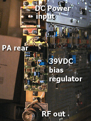
As amazing at it sounds, this is also a
1kW hot-swap PA. The
small 39V bias circuit board on the back ramps-up the
biasing for a smooth, surge-free power-up sequence.
The low current bias regulator also sources
the bias voltage to the PA transistors for several other
reasons. It also sets the broadband frequency
characteristics for a flat response across several TV
channels. This adjustment with pots located at each
transistor, is not typically needed in 5 kHz "narrow-band"
amateur service. This 39V regulator works off-of the primary 50 VDC B+ line.
As with
Motorola MSF-5000's and Spectras, you may want to replace the eleven blue electrolytic
caps.
Unlike the Motorolas, these don't typically leak but to be safe, it is a suggested Larcan factory update
after years of 24x7 operation... strictly optional.
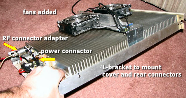
You may want to change-out the special hot-swap RF
connector (bottom) and B+
connector (top). The main RF output area is
simply the last rear-edge trace on a PC board so swapping
the special RF connector with an N-connector may be easiest |
 |
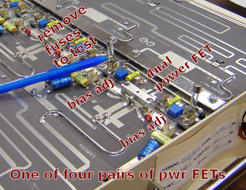
| The board uses four SRF-3943-2 FET's for 1kW video/SSB or 600W CW/FM. According to Larcan, and confirmed by Freescale Semiconductor who now owns this Motorola business, the '3943 is functionally equivalent to a MRF151G. M/A-COM has the build rights and is currently producing these. This device is rated at up to 175MHz, 300W (150W per FET). The MRF151G is available from rfparts.com for $110 - $120. If you really want the original SRF part marking, you can buy one from Larcan for $200. The datasheet for the MRF151G is in the links section above. Eight 10A fuses protect each half of the four dual-FETs.
The fuse removal will also allow for optimal biasing
of each transistor for multi-channel wideband TV
service. That adjustment is rarely required for ham operation
due to the 5 KHz maximum modulation bandwidth typically
used. |
|
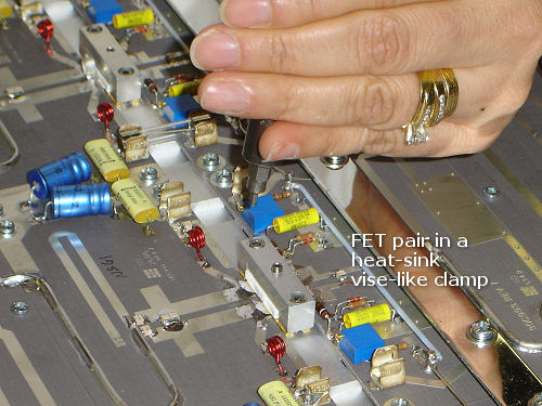
Replacing the SRF-3843-2 power FET is actually quite easy when using
standard practices.
Note the unsoldered tabs when the picture was taken.
Transmitter B+ runs on 50VDC but it will also run just
fine on 48 VDC. Current draw is
35A per PA module at full power so you'll need at least a 45A power
supply for 600 Watts. |
NOTE:
These tests in no way suggest out-of-band capabilities on behalf of
Larcan and this use is not supported by Larcan. These are
deliberate, non-normal tests when used outside of factory approved
limits for amateur radio uses.